Wire Guided Robot
This project found its inspiration in the robots used at industrial warehouses and harbors. These robots provide autonomous freight transport in and around the plant. Transportation routes can be preprogrammed or dynamic depending on the situation. This robot is guided through an induction wire which is installed beneath the driving surface. This means that the path the robot follows is hard-wired but there is no physical contact.
Controlling the robot can be done in two ways. The first mode is manual control by means of a tv-remote with RC5-communication. The second mode is automatic, making use of the induction wire to guide the robot.
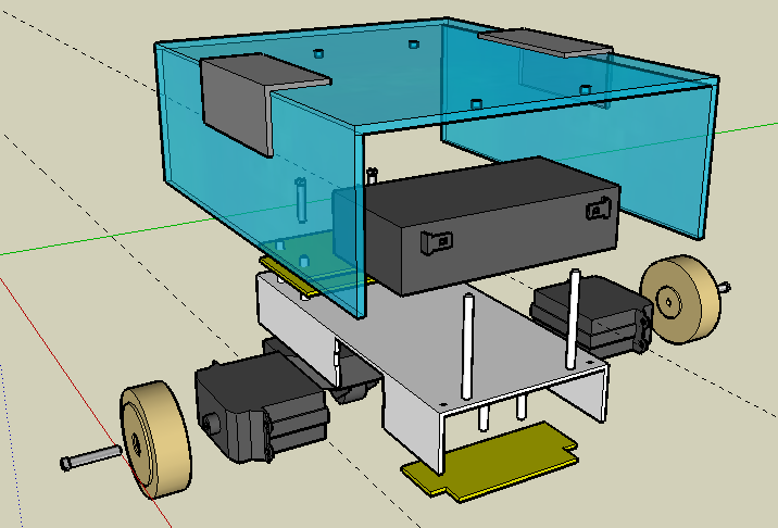
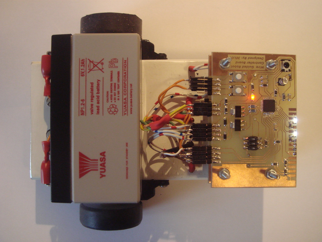
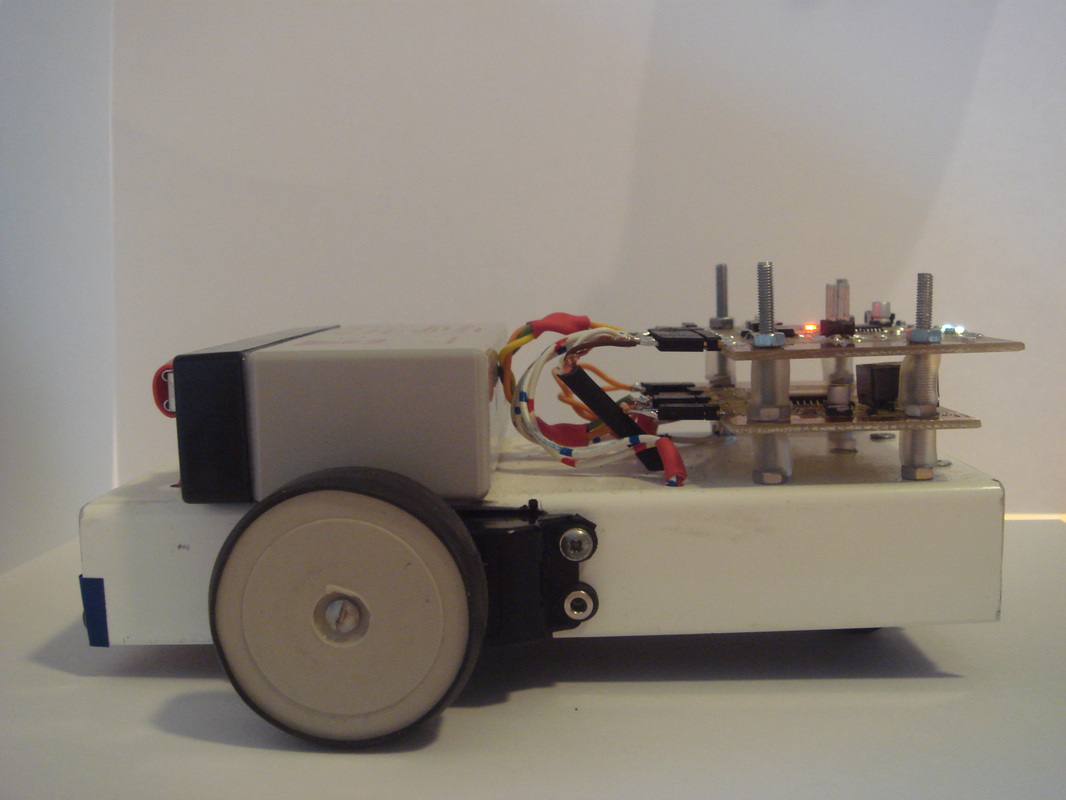
The frame of the robot is all aluminium and houses the DC-motors, the wheel assembly and the printed circuit boards. The DC-motors are two modified servo-motors from a small RC-car. The power supply and the main controller board are stacked on top of the robot, the circuit board with the induction sensors is located beneath the robot.
Power Supply
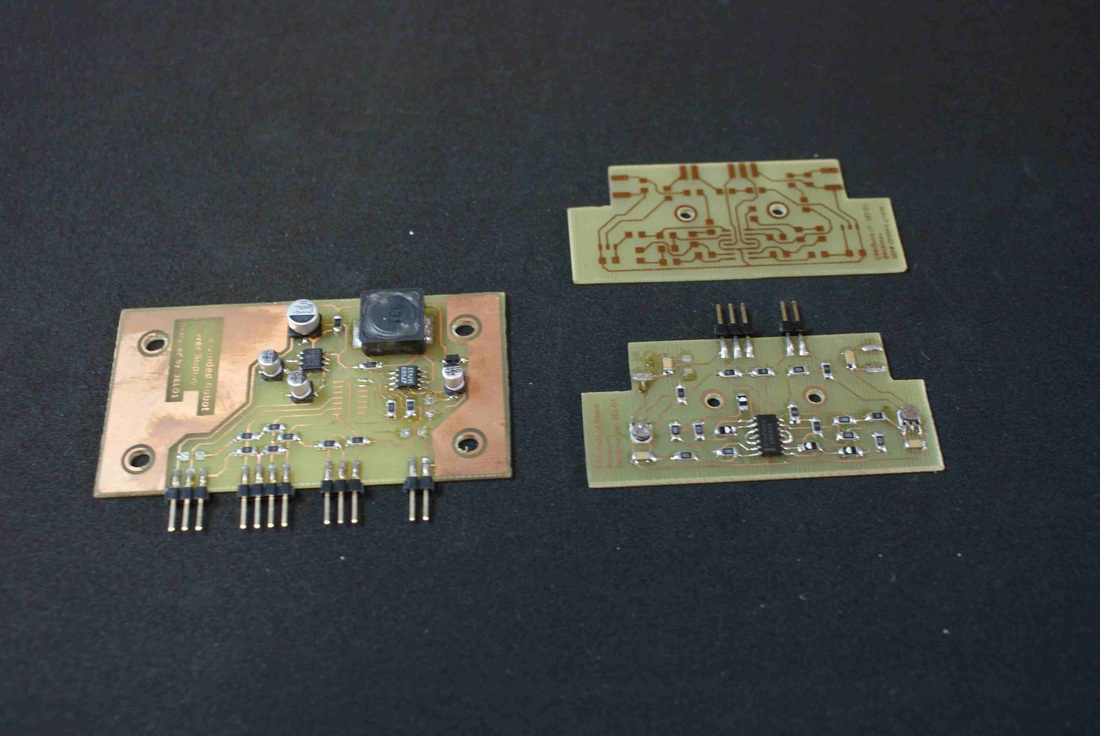
The power supply uses a 6V battery to create the necessary voltages, which are +3.3V, -3.3V and 6V. The positive and negative 3.3V are created by use of a LTC1474 step-down converter combined with a TC7662B charge pump. These voltages are used to power the induction sensors as well as the controller board. The DC-motors use the unconditioned 6V battery voltage.
Controller Board
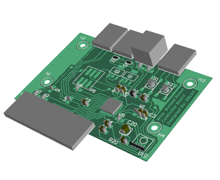
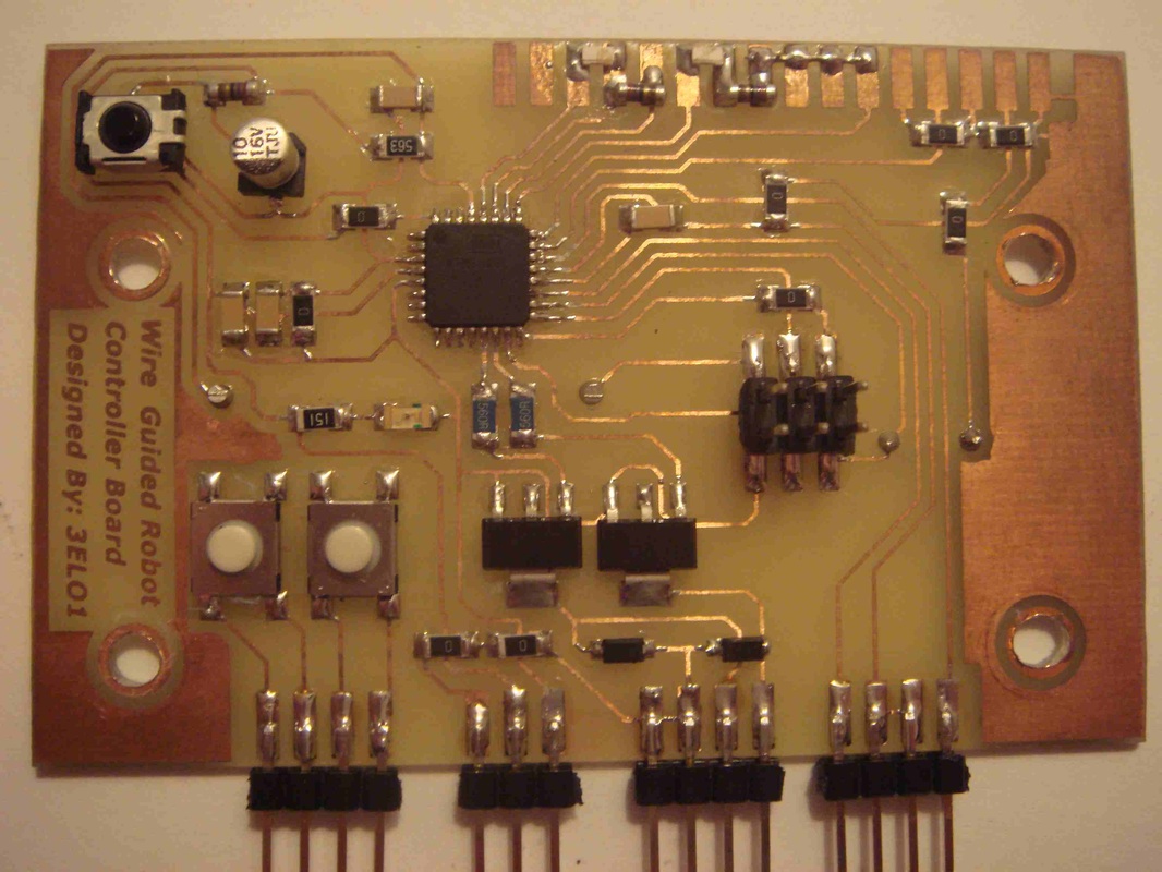
An ATmega8 is used to control the robot. On the controller board you'll find all the peripherals, such as a reset circuit, output drivers, infra-red sensor, LED's and switches. The ATmega is programmed to read the induction sensors, control the motors and implement the RC5-protocol.
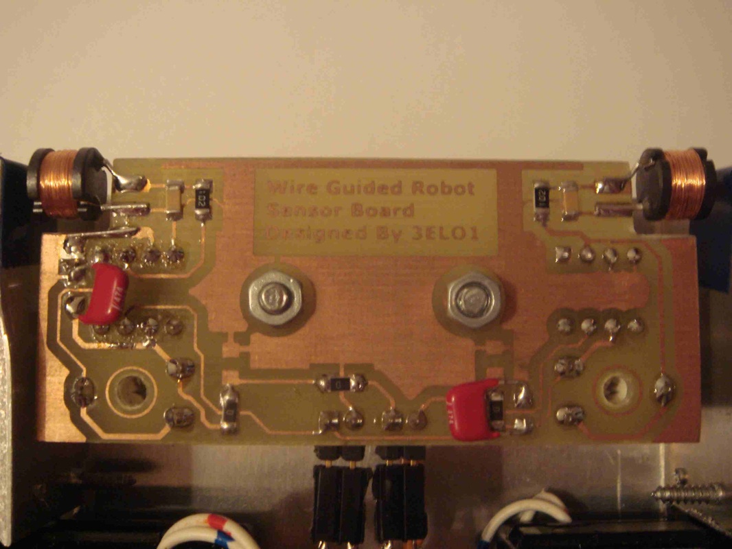
Induction Sensors
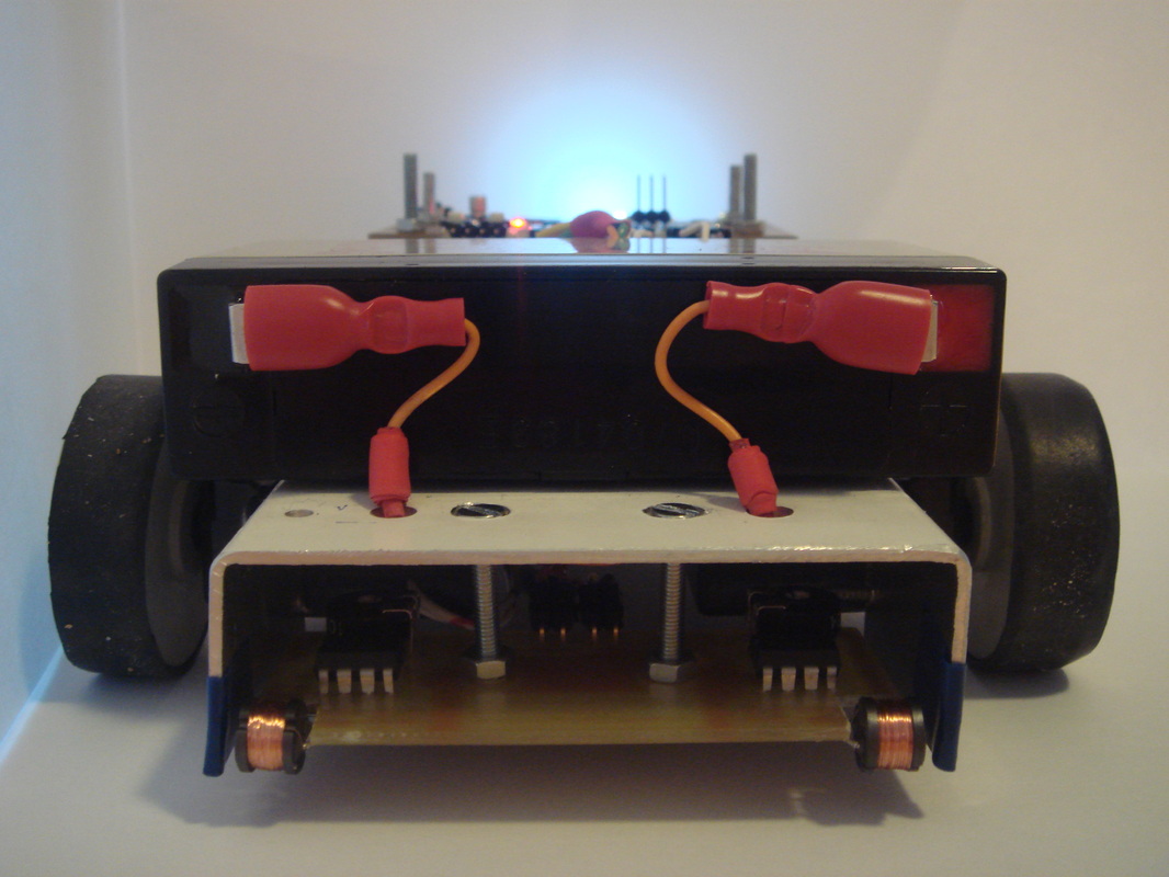
The robot navigates its way over the induction wire by means of two induction sensors. These sensors are located at each side of the robot. By comparing the two signals the location in relation to the induction wire can be calculated. For safety, the robot will stop if there is no signal present on both sensors.
Controlling the robot can be done in two ways. The first mode is manual control by means of a tv-remote with RC5-communication. The second mode is automatic, making use of the induction wire to guide the robot.
The frame of the robot is all aluminium and houses the DC-motors, the wheel assembly and the printed circuit boards. The DC-motors are two modified servo-motors from a small RC-car. The power supply and the main controller board are stacked on top of the robot, the circuit board with the induction sensors is located beneath the robot.
Power Supply
The power supply uses a 6V battery to create the necessary voltages, which are +3.3V, -3.3V and 6V. The positive and negative 3.3V are created by use of a LTC1474 step-down converter combined with a TC7662B charge pump. These voltages are used to power the induction sensors as well as the controller board. The DC-motors use the unconditioned 6V battery voltage.
Controller Board
An ATmega8 is used to control the robot. On the controller board you'll find all the peripherals, such as a reset circuit, output drivers, infra-red sensor, LED's and switches. The ATmega is programmed to read the induction sensors, control the motors and implement the RC5-protocol.
Induction Sensors
The robot navigates its way over the induction wire by means of two induction sensors. These sensors are located at each side of the robot. By comparing the two signals the location in relation to the induction wire can be calculated. For safety, the robot will stop if there is no signal present on both sensors.
|
|
|